
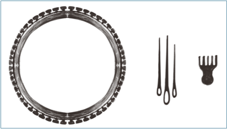
Chapter 2: Designing, Modelling, and 3D Printing a Mini-Loom
YongHong Chen
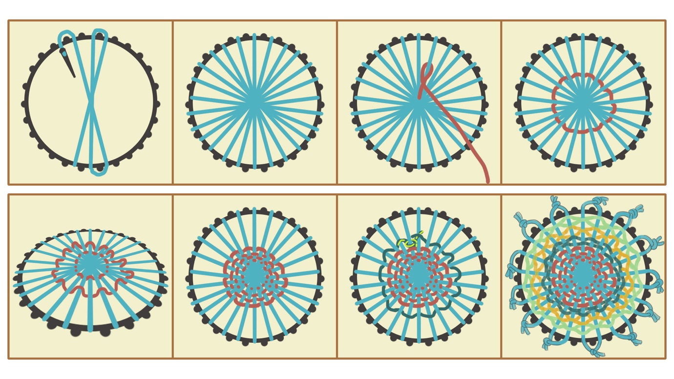
2.1 Designing the Miniature Loom (Sketches by hand or using Photoshop)
Start by drafting the structure of the loom. Note the following considerations:
- If the dataset is based on weekly records, the number of notches or pegs should ideally be a multiple of seven.
- The loom must fit within the build volume of the 3D printer. In general, the maximum dimensions should be kept under 25 cm.
- All printable components must have a thickness of at least 0.5 cm to ensure structural stability and avoid print failure.
2.2 Creating a Miniature Weaving Loom 3D Model in Blender
This section outlines the process of designing a Mini-loom in Blender. Follow these steps by referring to the corresponding figures.
-
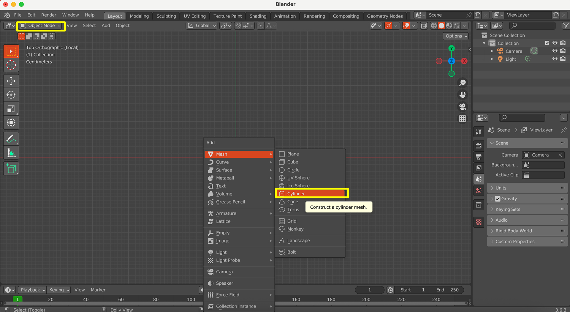
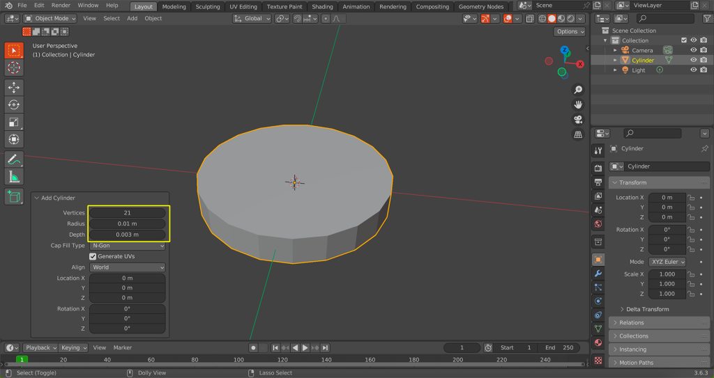
Create a Cylinder:
Start by pressing the shortcut Shift + A to bring up the ‘Add‘ menu. Select ‘Mesh‘ and then ‘Cylinder‘ to add a basic cylinder to your scene.
-
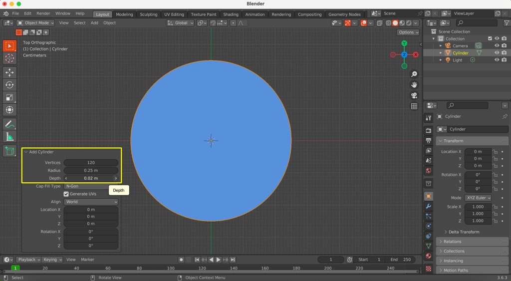
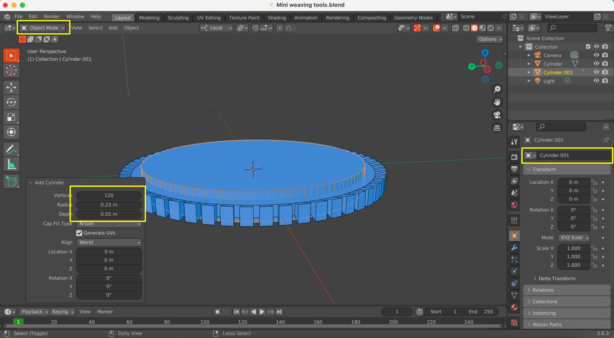
Adjust Dimensions:
After creating the cylinder, adjust its dimensions. Set the X and Y dimensions to 0.25 metres and the Z (thickness) dimension to 0.02 metres. You can usually find these options in the ‘Add Cylinder‘ panel that appears in the bottom-left corner of the viewport after creation.
-
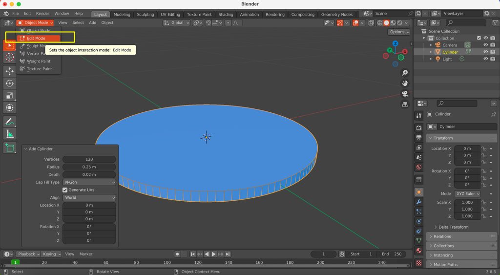
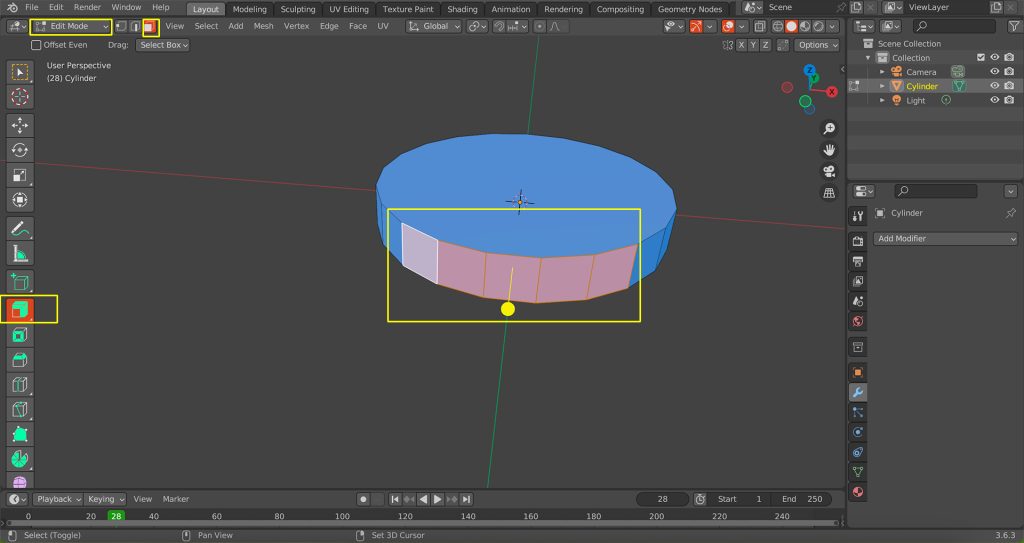
Switch to Edit Mode:
With the cylinder selected, switch from ‘Object Mode‘ to ‘Edit Mode’. You can do this by pressing the Tab key or by selecting ‘Edit Mode‘ from the dropdown menu in the top-left corner of the 3D viewport.
-
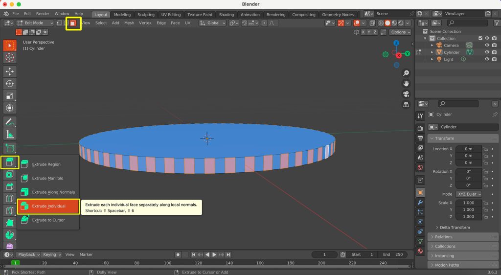
Select Faces and Extrude Individual:
In ‘Edit Mode‘, ensure you are in ‘Face Select‘ mode (you can click the ‘Face Select‘ icon in the header or press the 3 key). Now, select faces with an interval (i.e., select one face, skip one, select the next, and so on around the circular edge of the cylinder). Once selected, press and hold the Extrude button, then select Extrude Individual.
-
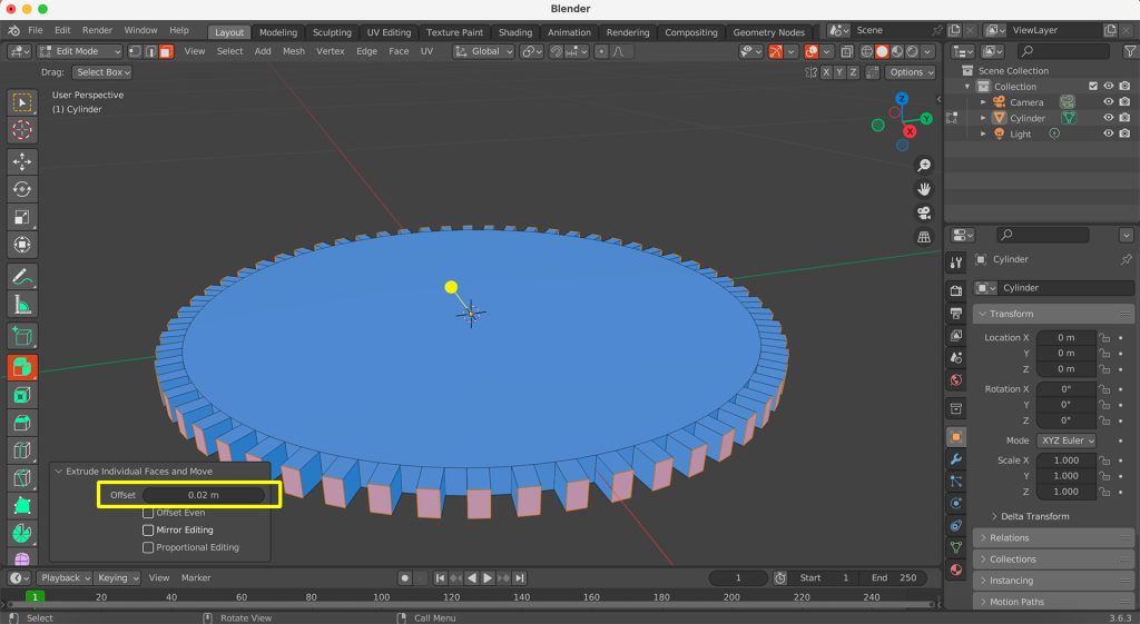
Extrude Along Normals:
Extrude the selected faces outwards along their own normals. Adjust the extrusion distance to 0.02 metres.
-
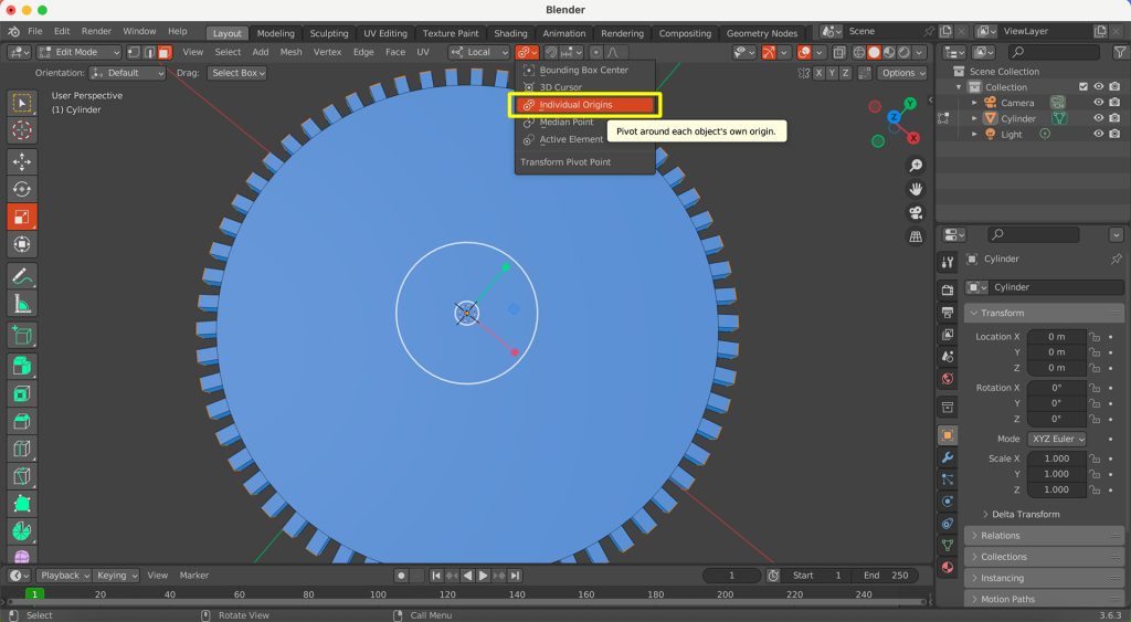
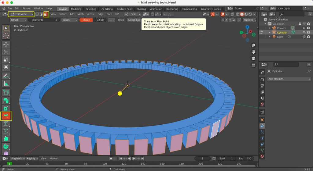
Modify Transform Pivot Point:
To ensure subsequent scaling or transformations apply correctly to each individual, change the ‘Transform Pivot Point‘ to ‘Individual Origins‘.
-
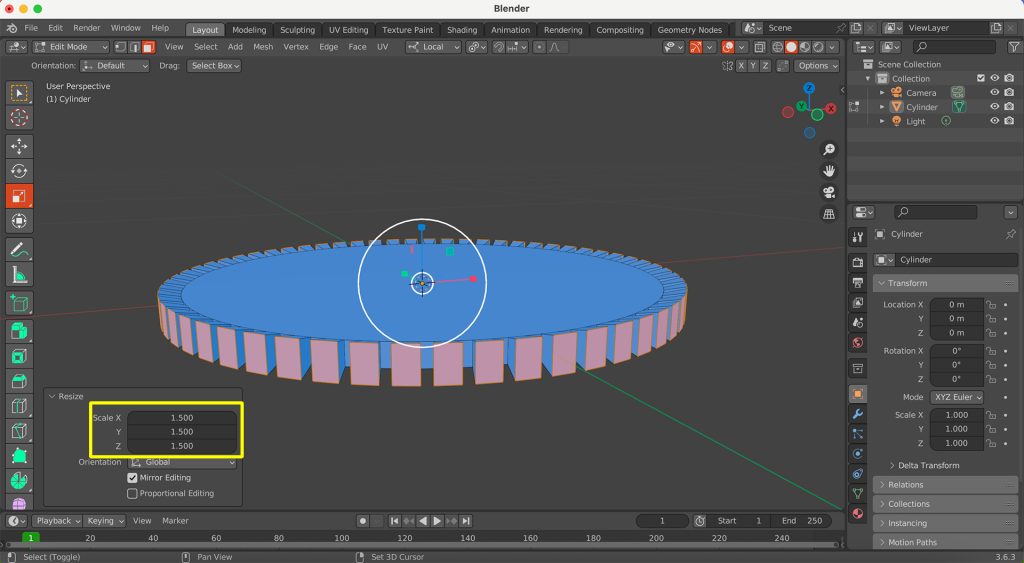
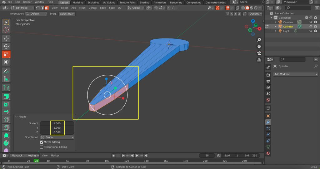
Scale Selected Faces:
With the same alternating faces still selected, scale them up 1.5 times. This shape can make the fabric’s basic structure more secure and convenient for knitting operations.
-
Exit Edit Mode and Create Second Cylinder:
Exit ‘Edit Mode’ by pressing Tab to return to ‘Object Mode‘. Now, create another cylinder using the same method: Shift + A, then ‘Mesh‘ > ‘Cylinder‘. This second cylinder should have a smaller diameter than your first (the ‘gear‘ object), but it should be taller. Position it so it passes through the centre of the gear.
-
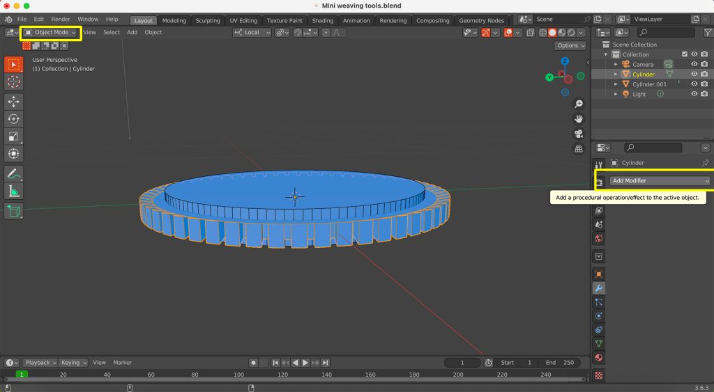
Select Large Gear and Add Modifier:
Select your larger, gear-shaped object. Then, go to the ‘Modifier Properties‘ tab in the Properties Editor (the wrench icon) and click ‘Add Modifier‘.
-
Add Boolean Modifier:
From the ‘Generate‘ column of the ‘Add Modifier‘ menu, select ‘Boolean‘.

-
Configure Boolean Modifier:
In the Boolean modifier panel, ensure the ‘Operation‘ is set to ‘Difference‘. Then, use the ‘Eyedropper‘ tool next to the ‘Object‘ field and click on the second cylinder you created (it will likely be named ‘Cylinder.001’) in the 3D viewport or the Outliner. The volume of the second cylinder will be subtracted from the first.

-
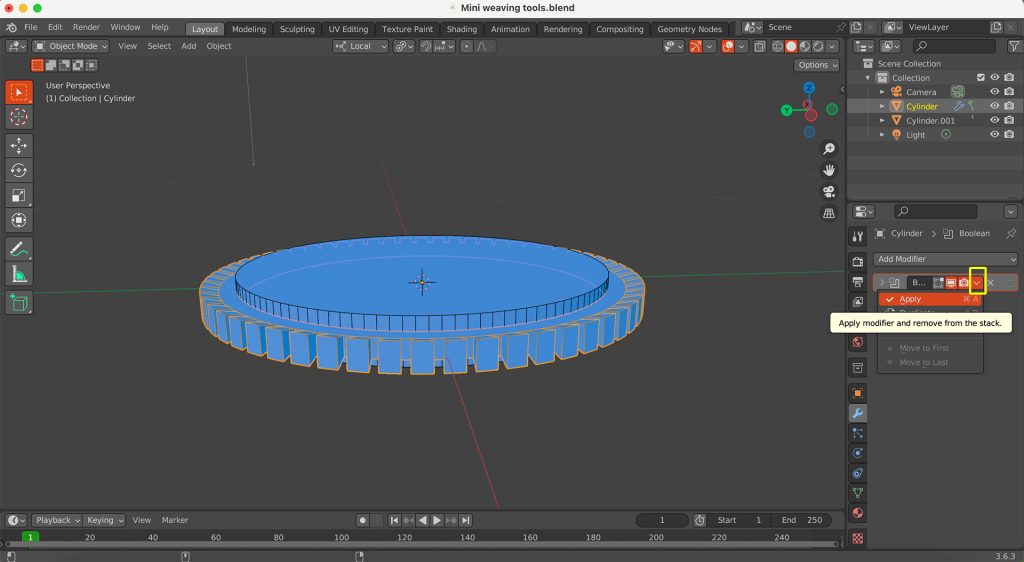
Apply Modifier:
Once you’re satisfied with the preview, apply the Boolean modifier. You can do this by clicking the small down arrow next to the modifier’s name and selecting ‘Apply‘.
-
Delete Second Cylinder:
After applying the Boolean modifier, select the second cylinder (‘Cylinder.001’), which you used for the subtraction, and press the X key to delete it.

-
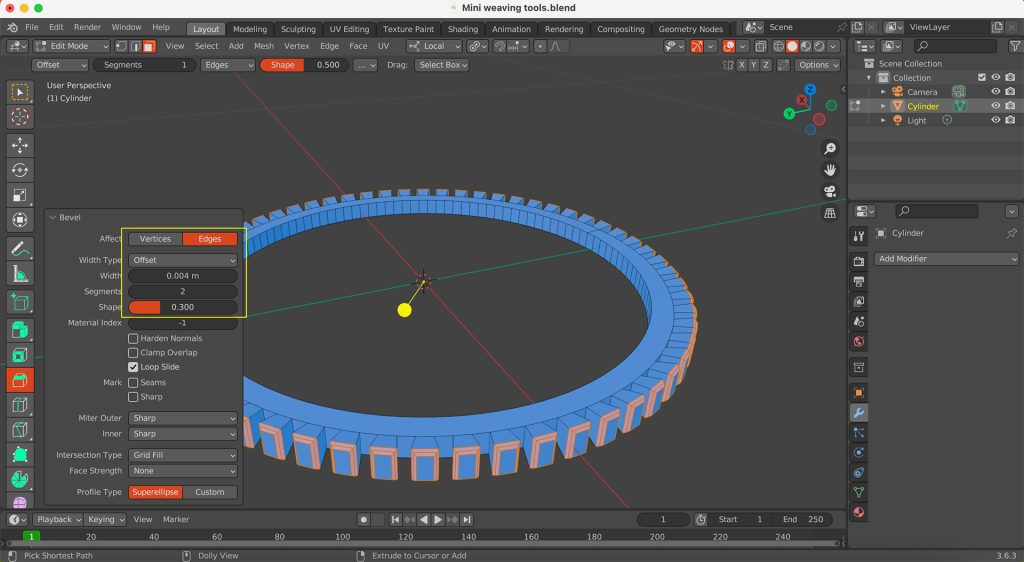
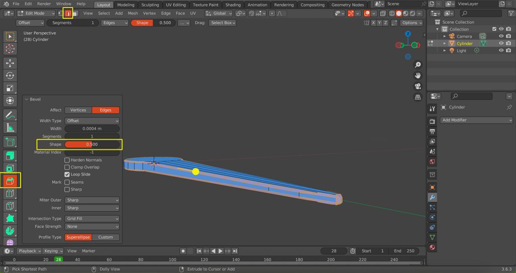
Bevel Outer Edge:
Switch back to ‘Edit Mode‘ (Tab key). Select all the faces on the outermost edge of your gear. Then, use the ‘Bevel‘ tool.
-
Adjust Bevel Parameters:
Now, set the parameters for the bevel. This might involve adjusting the ‘Segments‘ for smoothness, or the ‘Width‘ of the bevel.
-
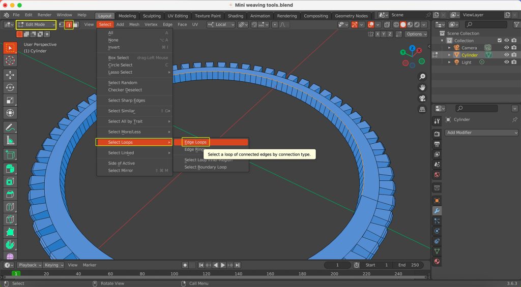
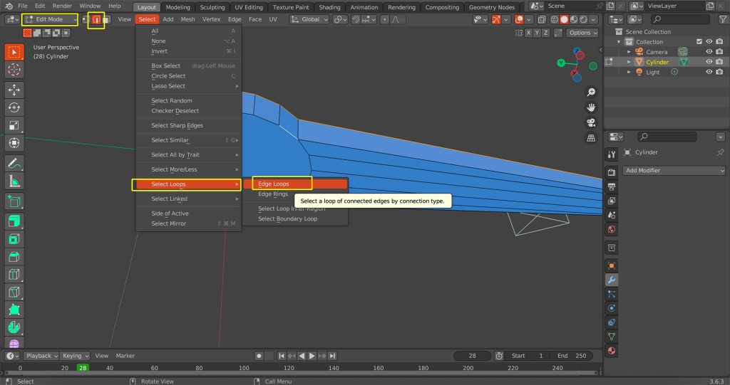
Select Inner Edge Loop:
Now, switch to ‘Edge Select‘ mode (press 2 on keyboard). Select the inner edge loop (the circular edge around the newly created hole). You can usually do this by holding Alt and clicking on one of the edges in the loop. If you do not select the complete edge line at once, you can press the shift key to select more target lines.
-
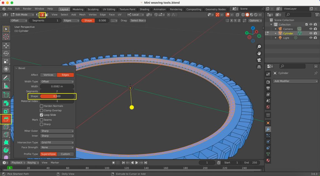
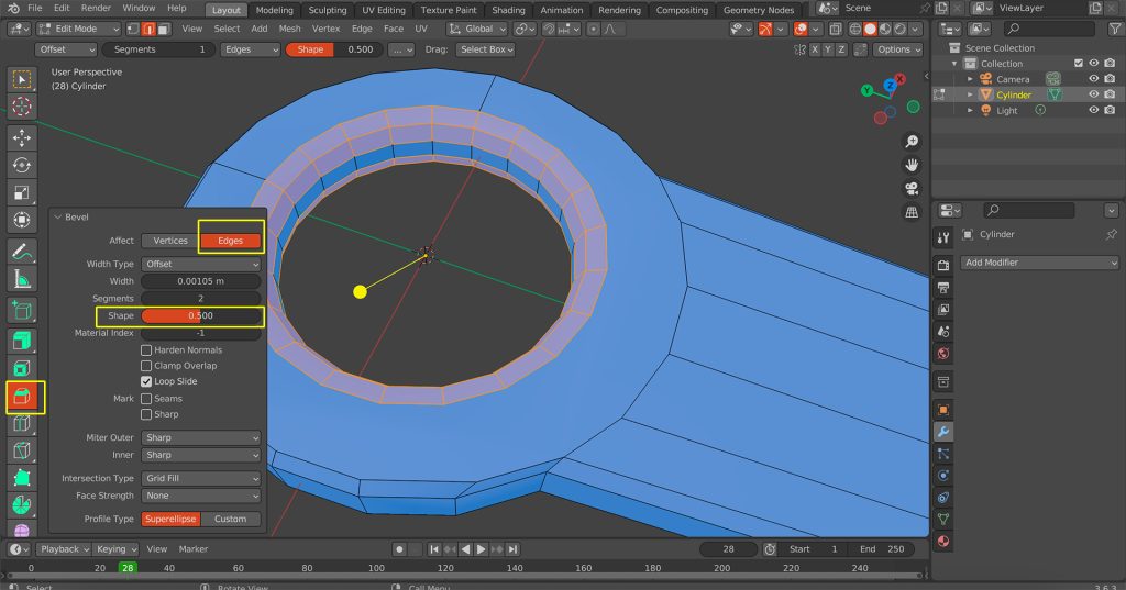
Bevel Inner Edge and Adjust Shape:
Apply the ‘Bevel‘ tool to this inner edge loop as well. Additionally, modify the ‘Shape‘ parameter in the Bevel options to refine its profile.
-
Recalculate Normals (Crucial for STL Export):
Before exporting your model to STL format, it’s vital to ensure the normals are correctly oriented. In ‘Edit Mode‘, select all faces on your model. Then, right-click anywhere in the viewport, go to ‘Normals‘, and select ‘Recalculate Outside‘. This ensures that all faces are pointing outwards. This step is critical because it ensures:
- Successful 3D printing.
- The model is geometrically sound and free of errors.
- Other software can correctly recognise and process your model.

-
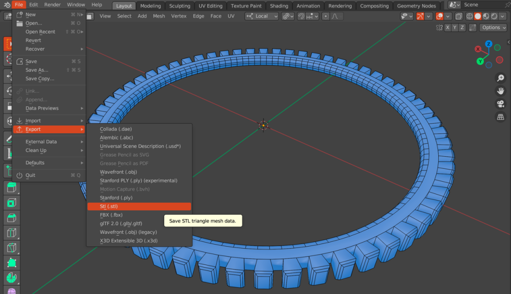
Export to STL Format:
With your model correctly set up and its normals recalculated, you are now ready to export it. Go to the ‘File‘ menu at the top-left of the Blender interface, then select ‘Export‘, and choose ‘STL (.stl)‘ from the list of file formats. A file browser window will appear; select a folder location to save your STL file, then name it.
Creating a Weaving Needle 3D Model in Blender
This section will guide you through the process of creating a 3D model of a weaving needle. Follow these steps while referring to the corresponding figures.
-
Create a Cylinder:
Begin by adding a new Cylinder to your scene by pressing Shift + A, then selecting ‘Mesh‘ and ‘Cylinder‘.
-
Scale and Position the Cylinder:
Adjust the dimensions of the cylinder to form the initial body of the needle. Scale it along the Z-axis to make it longer, and possibly slightly adjust its diameter.
-
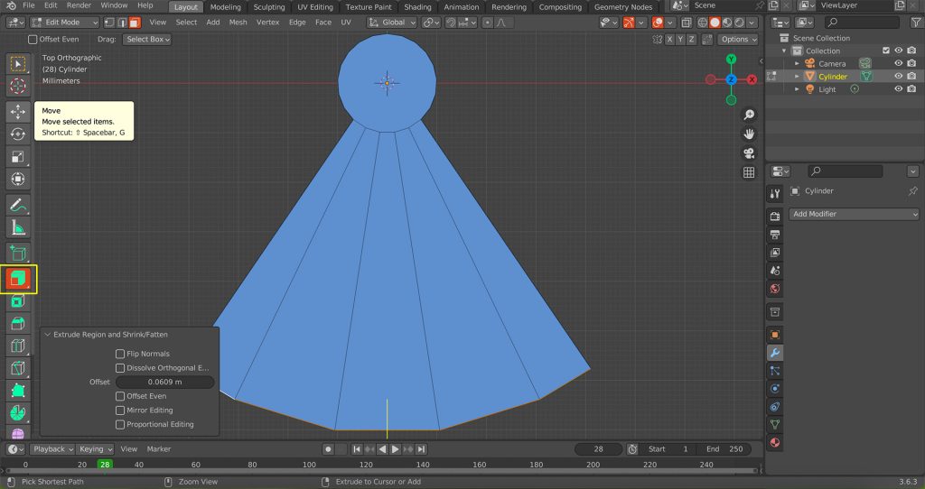
Extrude and Taper the Needle Body:
Switch to ‘Edit Mode‘ (Tab key). Select the top face of the cylinder and extrude it upwards. As you extrude, gradually scale down the extruded sections to create the tapered shape of the needle’s tip. Repeat this process multiple times to achieve a smooth point.
-
Refine the Needle Point:
Continue extruding and scaling the tip until your needle is pointed. Focus on creating smooth transitions between the extruded segments.
-
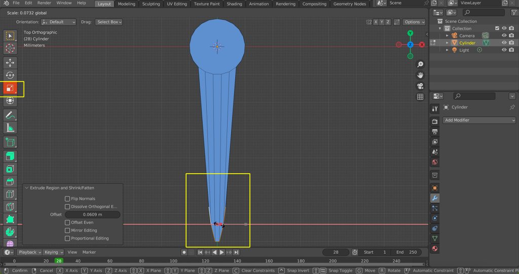
Flatten Needle Tip Profile:
In ‘Edit Mode‘, select approximately 5 side faces near the tip of the needle. Scale these selected faces down (e.g., along the X-axis if the needle is aligned with Y) to make the overall needle head flatter (This shaping helps the needle glide more smoothly when weaving thread).
-
Select Dual Outer Edge Loops for Bevel:
In ‘Edit Mode‘, switch to ‘Edge Select‘ mode (press 2 on keyboard). Select one of the outer edge loops along the length of the needle’s main body. Then, hold down Shift and select the corresponding outer edge loop on the opposite side of the needle. This prepares the edges for a simultaneous bevel operation.
-
Apply Bevel to Outer Contours and Adjust Parameters:
With both outer edge loops selected (from step 25), apply the ‘Bevel‘ tool (Ctrl + B and drag). As you apply the bevel, adjust its parameters such as ‘Segments‘ for smoothness and ‘Width’ to achieve the desired roundedness. These options appear in the ‘Adjust Last Operation‘ panel (usually in the bottom-left of the viewport or by pressing F9). This smooths the needle’s main profile.
-
Create Needle Eye using Boolean Difference:
- First, exit ‘Edit Mode‘ (Tab key) and create a new cylinder (Shift + A > Mesh > Cylinder). Scale and position this new cylinder to overlap the needle exactly where you want the eye to be.
- Now, select your needle object. Go to the ‘Modifier Properties‘ tab and click ‘Add Modifier‘. Choose ‘Boolean‘ from the ‘Generate‘ column.
- In the Boolean modifier panel, set the ‘Operation‘ to ‘Difference‘. Use the ‘Eyedropper‘ tool next to the ‘Object‘ field and click on the new cylinder (your cutter object, likely named ‘Cylinder.001’) in the 3D viewport or Outliner. This will subtract the volume of the cutter from the needle.
- Finally, apply the Boolean modifier (click the small down arrow next to the modifier’s name and select ‘Apply‘ or Ctrl + A while hovering). Then, select and delete the temporary cylinder (press the X key).

-
Bevel Inner Edge of Needle Eye:
Switch back to ‘Edit Mode‘ (Tab key). Select the inner edge loop of the newly created needle eye (the circular edge of the hole). Apply the ‘Bevel‘ tool (Ctrl + B) to this inner edge. Adjust the bevel to make it slightly rounded or smoother. This small bevel helps to reduce friction and potential wear on yarn or cotton thread passing through the eye.
-
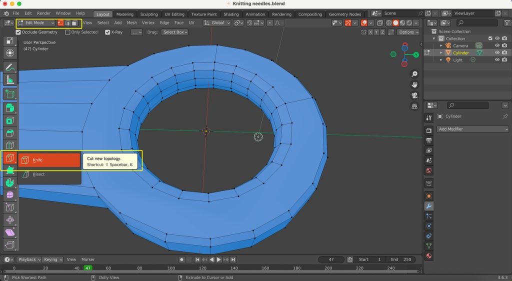
Subdivision Surface Preparation (Quadrangulation):
If you plan to use a Subdivision Surface modifier for a smoother result without deformation, your mesh must consist entirely of four-sided faces (quads).
- Switch to ‘Edit Mode‘ (Tab key).
- Go to ‘Vertex Select‘ mode (press the 1 key).
- Utilise the ‘Knife Tool‘ (As shown in Figure 2.2.29) to cut across any areas with N-gons (faces with more than four vertices) or triangles, subdividing them into quads. Ensure that all faces in your model become quadrilaterals. This step is vital to ensure that the Subdivision Surface modifier only smooths the mesh.
-
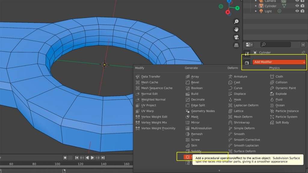
Apply Subdivision Surface Modifier (Optional):
Once your mesh is fully quadrangulated, you can apply a ‘Subdivision Surface’ modifier from the ‘Modifier Properties’ tab (wrench icon) to smooth the model.
-
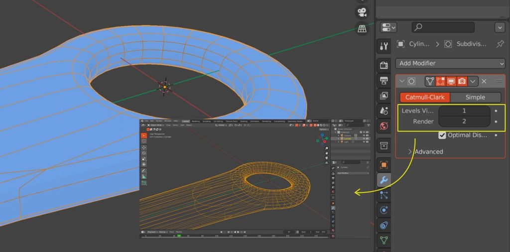
Apply Smoothing:
Start with 1 or 2 levels in the ‘Viewports’ setting for a smooth appearance and apply subdivision. Right-click on the needle object and select ‘Shade Smooth’. This will ensure the surface shading appears smooth.
-
Recalculate Normals (Crucial for STL Export):
Repeat what was done during Step 18, by going into ‘Edit Mode‘ and selecting all faces on your model. Then, right-click anywhere in the viewport, go to ‘Normals‘, and select ‘Recalculate Outside‘. Ensure your model’s normals are correctly oriented to guarantee successful 3D printing and avoid geometric errors.
-
Export to STL Format:
Once your needle model is complete and its normals are correctly calculated, export it to the STL format for 3D printing. Repeat what was done during Step 19, by going into the ‘File‘ menu at the top-left of the Blender interface, then select ‘Export‘, and choose ‘STL (.stl)‘ from the list of file formats. A file browser window will appear, allowing you to choose a location to save your STL file and give it a name.
2.3 3D Printing Preparation and Setup
This process involved the use of Ultimaker Cura for slicing the digital models and preparing them for the designated 3D printer.
Hardware and Software Utilised:
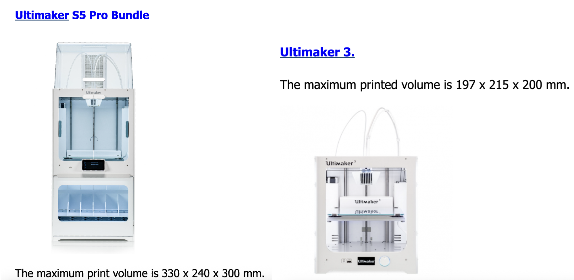
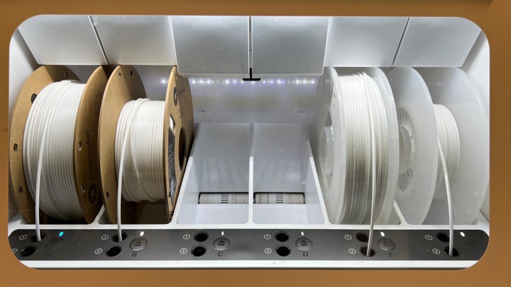
- 3D Printer: The Ultimaker S5 was selected for its reliability, precision, and dual extrusion capabilities.
- Slicing Software: Ultimaker Cura was used to convert the 3D models into printable G-code, allowing for precise control over print settings such as layer height, infill density, and support generation.
Materials Employed:
- Main Material: Polylactic Acid (PLA) was chosen as the primary build material. PLA is a biodegradable thermoplastic known for its ease of printing, good dimensional stability, and suitability for prototyping, making it ideal for the initial iterations of the micro weaving loom (Wikipedia, 2025).
- Support Material: Natural Polyvinyl Alcohol (PVA) was utilised as the soluble support material (Regemat3D, 2025).
- UltiMaker Breakaway: This non-soluble, mechanically removable support material was used for less complex support structures or when faster post-processing was desired. It is engineered to detach cleanly from the printed part. Learn more at ultimaker.com
To prepare the models for precise 3D printing, the slicing process was conducted in Ultimaker Cura, tailored to the characteristics of each model. Two different 3D printers were used: the Ultimaker S5 for the Mini Weaving Tools, and the Ultimaker 3 for the Knitting Needles and Weaving Comb. The following section outlines the exact configuration steps applied to each.
Model 1: Mini Weaving Tools
-
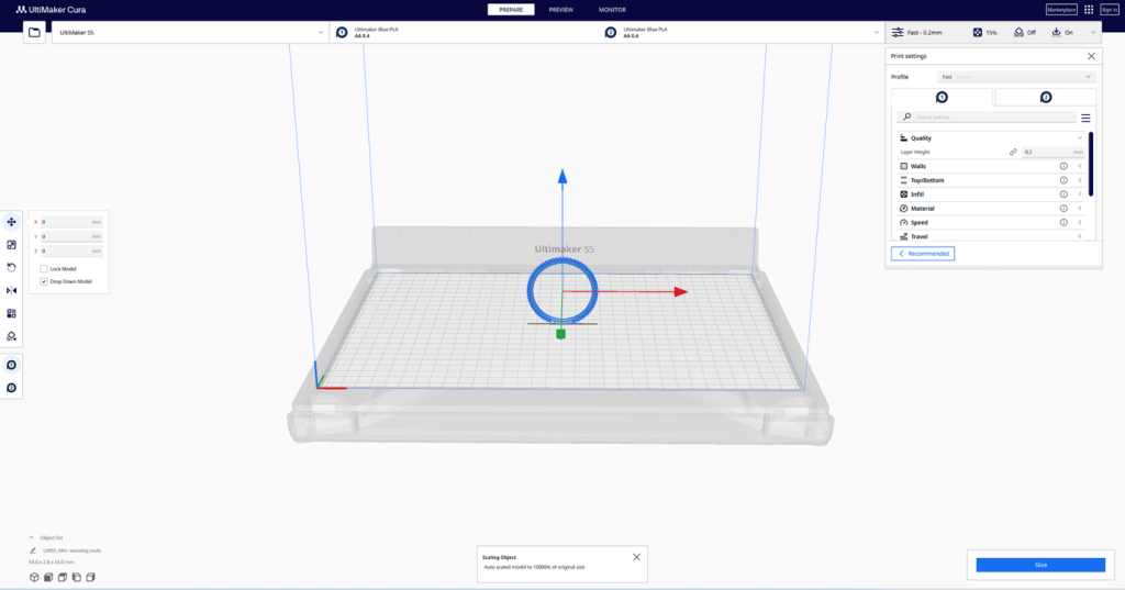
Importing and Reorienting the Model
- Open Ultimaker Cura and import Mini weaving tools.stl.
- Upon import, you may notice the scale differs from Blender. The model must be laid flat on the build plate to ensure proper adhesion and structural integrity.
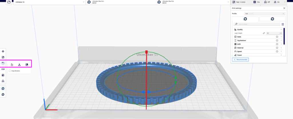
- Use the Rotate Tool to rotate the model along the X-axis, positioning it so it lies completely flat on the platform.
-
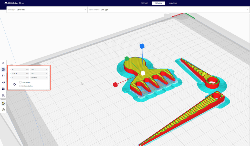
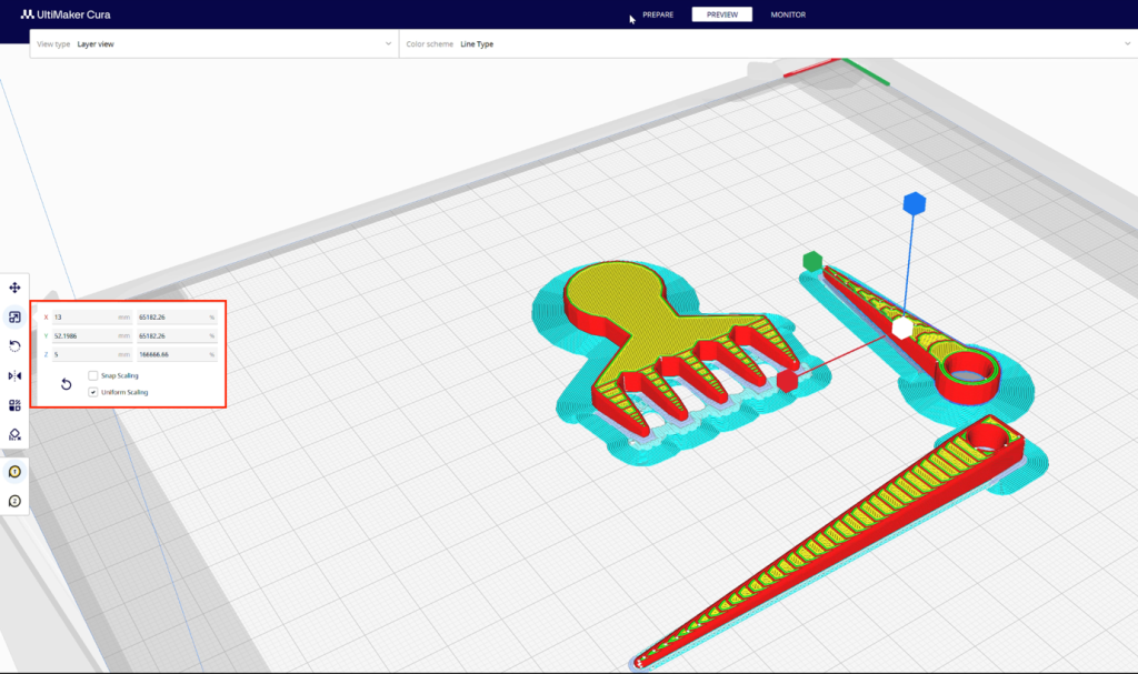
Rescaling the Model
- Activate uniform scaling, and adjust the model’s dimensions so that it fits within a circle of approximately 20 cm in diameter.
- This size was selected to match the proportion of a handheld weaving frame while maintaining good print resolution and structural clarity.
-
Material and Print Core Configuration
- Material: Generic PLA
- Print Core: AA 0.4 mm for both extruders
- Support Material: White Breakaway assigned to Extruder 2
-
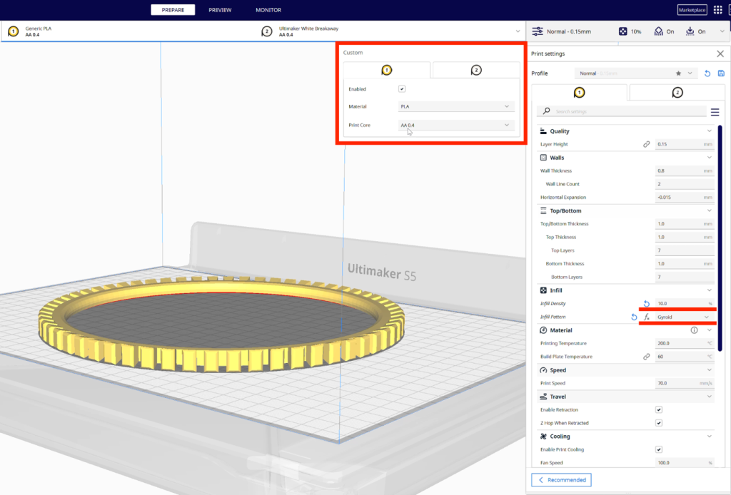
Basic Print Settings Configuration
Navigate to the ‘Custom’ tab to access detailed print parameters:
- Material: Select Generic PLA
- Print Core: AA 0.4 mm
- Infill Density: Set to 10%
- Infill Pattern: Choose Gyroid (offers balanced strength and flexibility)
- Enable Support Generation: ✔️ (tick the box)
- Support Extruder: Select Extruder 2 (White Breakaway material)
- Support Placement: Set to Touching Buildplate
- Build Plate Adhesion Extruder: Set to Extruder 1
- Enable Prime Tower: ❌ (untick to reduce unnecessary filament use)
This configuration ensures minimal support waste and reliable part quality, especially for the fine-weaving teeth.
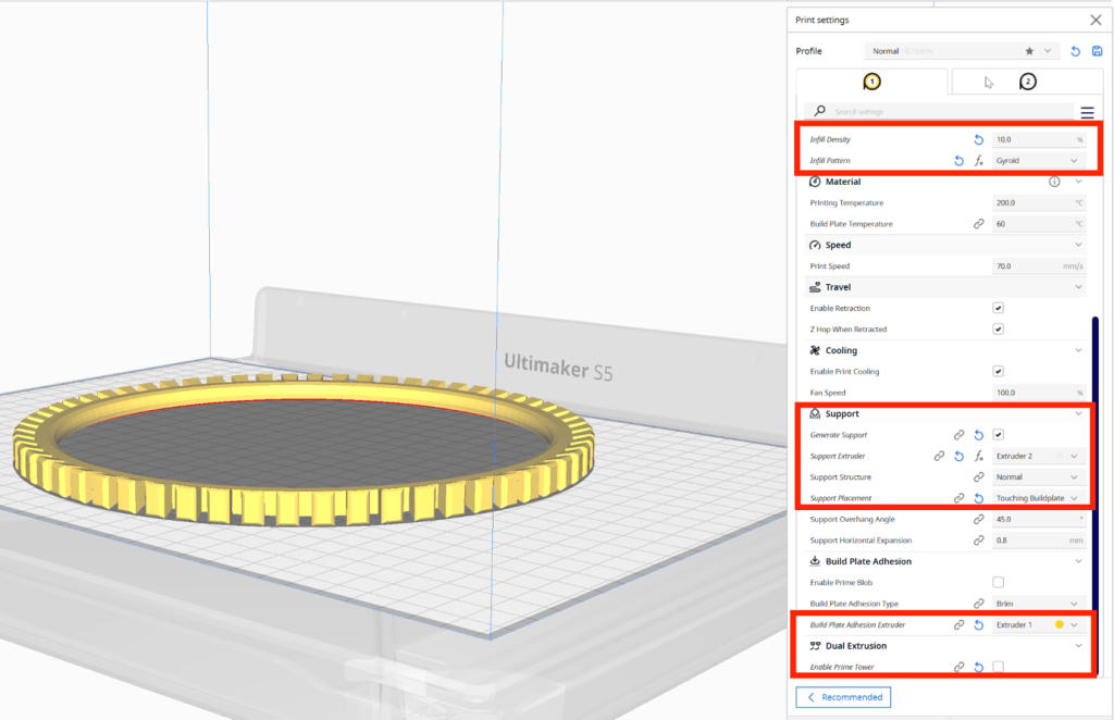
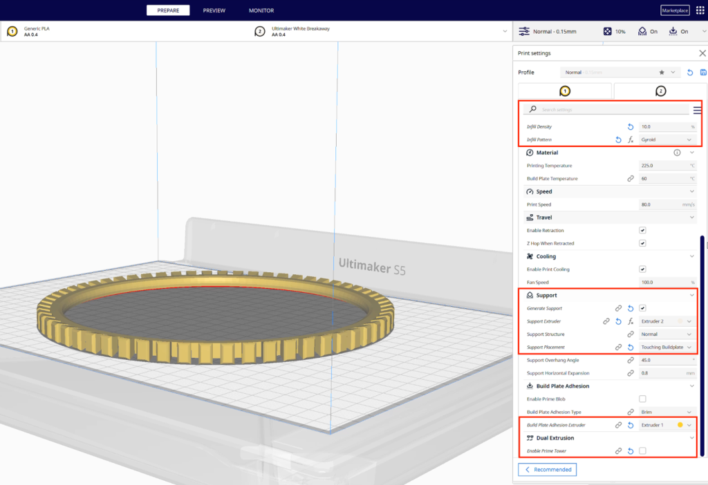
- Support Structure Settings
- Material: White Breakaway
- Print Core: AA 0.4 mm
- Infill Density: Maintain at 10%
- Infill Pattern: Gyroid
- Support Settings:
Generate Support: ✔️
Support Extruder: Extruder 2
Support Placement: Touching Buildplate
- Build Plate Adhesion:
Extruder: Extruder 1
Prime Tower: ❌ (Disable)
This setup provides a clean support structure that can be manually removed without damaging the small-scale design.

Model 2: Knitting Needles and Weaving Comb
-
Importing and Scaling the Model
- Launch Ultimaker Cura and import the .stl file.
- Upon import, inspect the layout of the needles and comb to ensure they are positioned optimally. Due to the elongated shape of the knitting needles, they should be placed flat on the build plate to prevent warping or failed adhesion.
- Use Uniform Scaling to proportionally resize the model. The overall dimensions should remain within the printable area of the Ultimaker 3, ideally suited to a small handheld tool size.
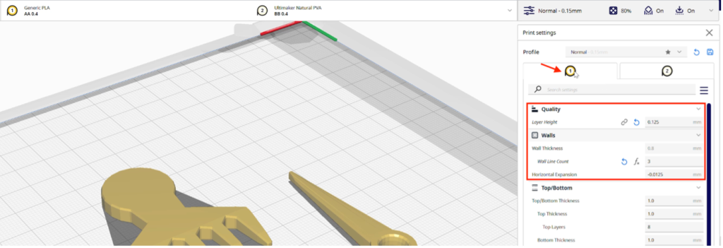
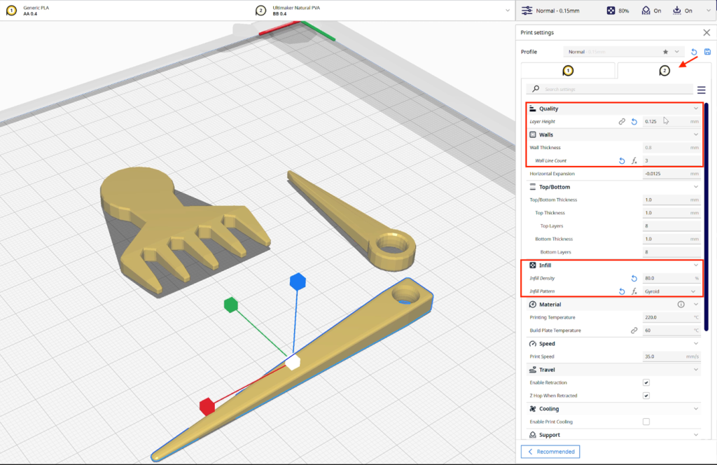
2. Basic Print Settings Configuration
Navigate to the ‘Normal’ tab in Ultimaker Cura and adjust the following settings:
- Layer Height: Set to 0.125 mm to achieve smooth surface quality and capture fine detail.
- Wall Line Count: Increase to 3 for added strength, particularly important for the thin shafts of the needles and comb teeth.
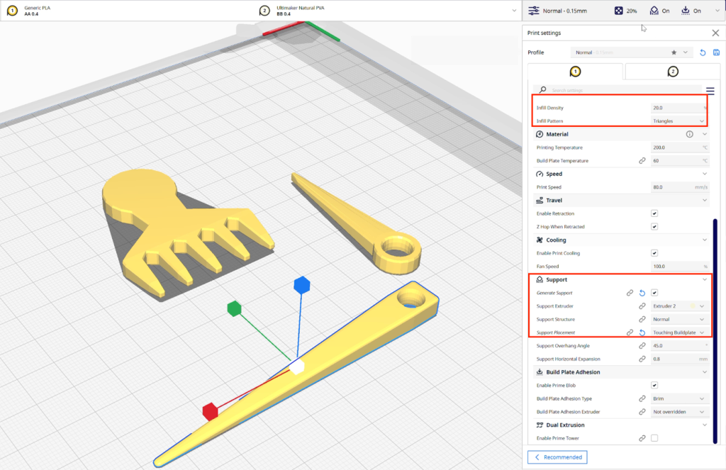
- Infill Density: Set to 20%, which balances structural rigidity and print efficiency.
- Infill Pattern: Choose Gyroid to maintain internal strength without unnecessary material usage.
- Generate Support: ✔️ (tick this to enable support structures)
- Support Placement: Select Touching Buildplate to ensure support is only generated beneath overhangs that need it.
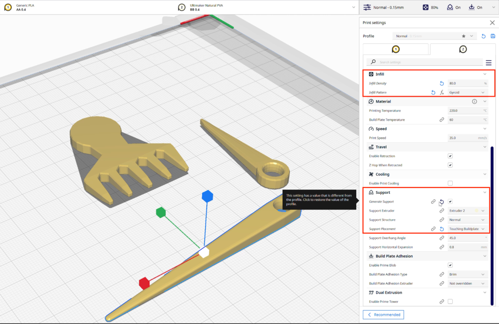
3. Support Structure Settings
Additional fine-tuning was done specifically for the support material to improve print quality and ease of removal:
- Layer Height (Support): Remains at 0.125 mm to ensure close integration with model surfaces.
- Wall Line Count (Support): Maintain at 3 to provide sturdy supports without brittleness.
- Infill Density (Support): Increase to 80% to ensure maximum reliability and contact under fine overhangs.
- Infill Pattern (Support): Continue with Gyroid to ensure strength without difficulty in dissolving.
- Generate Support: ✔️
- Support Placement: Touching Buildplate
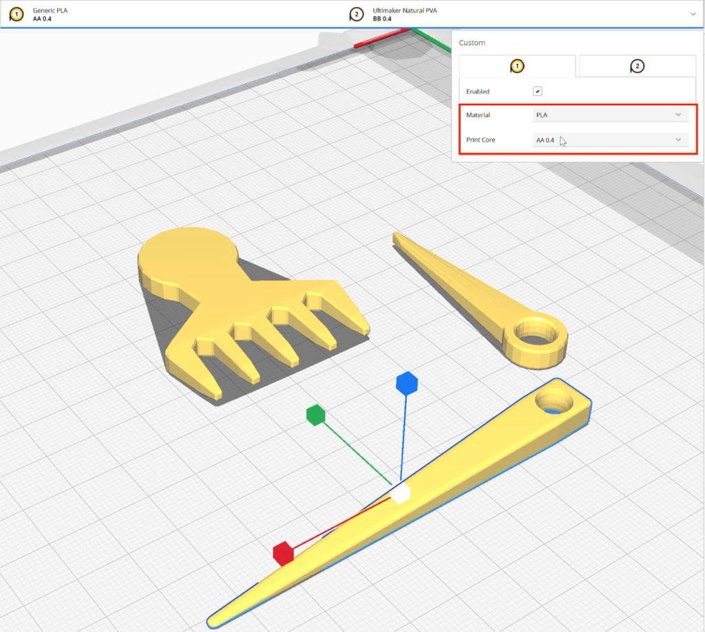
4. Material and Print Core Configuration
Material: Generic PLA assigned to Extruder 1
Print Core (Model): AA 0.4 mm
Support Material: Natural PVA, assigned to Extruder 2
Support Print Core: BB 0.4 mm
This combination of PLA and water-soluble PVA provides high-detail printing with clean, dissolvable support removal — ideal for intricate geometries.

Video 2.3 Demonstrates the setup of two 3D models in Ultimaker Cura.
Chapter 2.4 3D printing process and polishing finished products
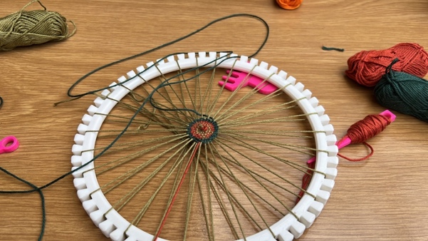
Video 2.4: The 3D Printing Process and Finishing the Model with Fine Sandpaper
This video demonstrates the complete 3D printing process, followed by detailed steps for finishing the printed object using fine-grit sandpaper. The purpose of sanding is to achieve a smooth surface finish, which is essential for the model’s functionality in textile work. A smoothly sanded surface helps prevent snagging or damage to cotton or wool yarns during the weaving or knitting process.
